Using a Unit Vector to Make a Cylindrical Foot Roll
Posted on April 03, 2012 - category: character-rigging
Here is a tutorial that will demonstrate how to use a Unit Vector to animate the pivot point of a cylinder so that the cylinder will roll on its bottom edge in any direction. I’m using this technique for the feet of my Mini Mammoth rig, but it could also be useful for robot feet, or adapted into different shapes for a variety of uses.
Here is a video of the foot rolling effect we are going to create:
Note: Be aware that my expression syntax may or may not play nicely with the html formatting you see, depending on how you are viewing this post. I have included a Maya 2012 scene file at the bottom of this post so you can download it and follow along. The final expression is included as a text file.
Notes about this tutorial:
- I am using locators as vectors so we can see what is going on. Once we are done prototyping this as an expression we can transform it into node connections that work directly with the attribute data rather than a daisy-chain of connected locators. This tutorial will just show the expression so you can get the idea.
- The order of the lines in your expression matters. Specifically, the foot’s rotation attributes will have to be animated before the pivots are translated in the expression. Otherwise I’ve found that you will sometimes get strange results. If your animation seems to jump or skip, keep this in mind.
- For simplicity, the way I build this ignores rotation in Y. Instead when I go to integrate this into a real rig, I’ll group this entire foot roll rig underneath a parent node and use that to rotate in Y in global space.
- The next step you could take would be to project the vector onto a curve using a closestPoint constraint. Shape the curve to match your character’s foot, and now you can have a foot roll in any shape you want!
So let’s get started
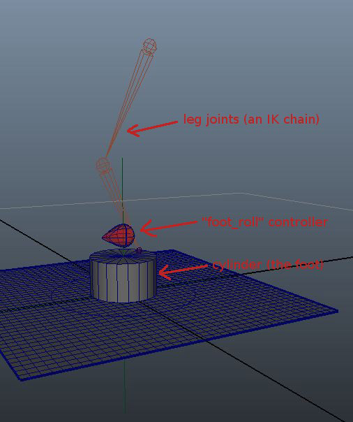
- Create a cylinder with a radius of 5 and move it up so that it rests at the ground plane.
- Create a joint at the bottom of the cylinder. Group the joint and call the group “foot_pivot”. The group will be controlled by the expression. Skin the cylinder to the joint.
- Create a “foot_roll” controller. This can be a locator or a curve icon or whatever. This is the controller that will rotate the foot.
- Create two locators. Name the first one “vector1” and the second one “normalized_vector1”.
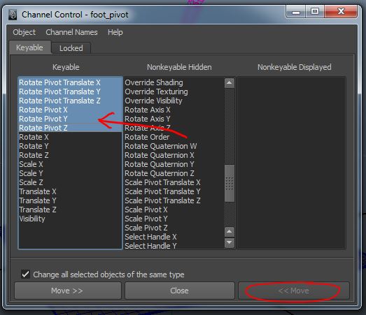
- Select the “foot_pivot” group. Go into Edit -> Channel Control and in the Nonkeyable Hidden column make the following visible and keyable:
Rotate Pivot X, Rotate Pivot Y, Rotate Pivot Z
Rotate Pivot Translate X, Rotate Pivot Translate Y, Rotate Pivot Translate Z
- The first step is to turn the rotation of the “foot_roll” control into XZ translation which we will feed into the pivot point of “foot_pivot”.
vector1.translateX = -foot_pivot.rotateZ;
vector1.translateZ = foot_pivot.rotateX;
// (note the negative value. This may change for you depending
// on your controllers orientation.)
When you rotate the “foot_roll” now “vector1” will travel along the ground plane pointing in the direction of the rotation. But the distance from the foot is wrong and it is not in a circular shape. So… - We arrive at the meat of this entire tutorial. To get a useful pivot we need to create a Unit Vector or a normalized vector which will always have the same length of 1 no matter which direction it is pointing.
If you aren’t familiar with vectors, this would be the same as having a 1-bone IK chain. As you move the effector around, the chain points in the correct direction, but stays the same length.
However, if you aren’t familiar with vectors, I highly suggest learning about them. They will open up a new world of ideas for you as a rigger or TD. http://www.rtrowbridge.com/blog/2012/03/442/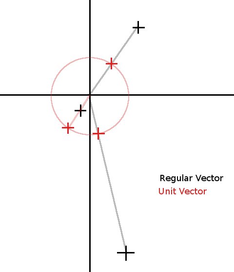
We’ll use the built-in unit() vector function in the Expression Editor. Later if you want to rebuild it with nodes, you can get the same functionality with the vectorProduct node and turning “Normalize output” to ON.vector $norm = unit(<<vector1.translateX,vector1.translateY,vector1.translateZ>>);
- Now we have a vector, so let’s drive the “normalized_vector” locator so we can see what it is doing. (We don’t need to use the Y-component.)
normalized_vector1.translateX = $norm.x
normalized_vector1.translateZ = $norm.z
- Ok, but now the problem is that our foot radius is 5 units and the Unit Vector is only 1 unit long. So let’s create a variable to multiply the unit vector which will be easy to edit if we need to use it on different sized cylinders. We add the following to the expression:
float $radius = 5.0;
normalized_vector1.translateX = $norm.x * $radius;
normalized_vector1.translateZ = $norm.z * $radius;
Now the “normalized_vector1” should be travelling in a circle around our foot as we rotate “foot_roll”. - Now this normalized vector is just for visualization or debugging purposes. Let’s connect that straight into the rotatePivotX and rotatePivotZ attributes of the “foot_pivot”. (the group that parents the foot joint.)
foot_pivot.rotatePivotX = $norm.x * $radius;
foot_pivot.rotatePivotZ = $norm.z * $radius;
- And finally, rotate the “foot_pivot”. (Note that this will go at the top of the expression. Putting it at the bottom caused erratic behaviour for me.)
foot_pivot.rotateX = foot_roll.rotateX;
foot_pivot.rotateY = 0;
foot_pivot.rotateZ = foot_roll.rotateZ;
Bring it all together and this is our final expression:
// Rotate the pivot_rotator to match the controller
foot_pivot.rotateX = foot_roll.rotateX;
foot_pivot.rotateY = 0;
foot_pivot.rotateZ = foot_roll.rotateZ;
float $radius = 5.0;
// Turn the controller rotation into XZ translation
vector1.translateX = -foot_pivot.rotateZ;
vector1.translateZ = foot_pivot.rotateX;
// Normalize the vector
vector $norm = unit(<<vector1.translateX,vector1.translateY,vector1.translateZ>>);
// Use the normalized coordinates to set the position of norm_vector
normalized_vector1.translateX = $norm.x * $radius;
normalized_vector1.translateZ = $norm.z * $radius;
// Animate the pivot_rotator pivot point to match the normalized vector
foot_pivot.rotatePivotX = $norm.x * $radius;
foot_pivot.rotatePivotZ = $norm.z * $radius;
(This step is optional or could be done differently.) - Another thing I like to do is connect the “foot_roll” translation to the “foot_pivot.rotatePivotTranslate”. Then you can translate the “foot_roll” to create sliding effects in parent space. So even though the foot roll will be rotated, moving forward in Z will slide the foot along the ground all with one control object.
**Update: Armin Halac of Robot Squids has created a video tutorial showing how you can build a set up like this that lets use you an arbitrary foot shape using only Maya nodes. Make sure to check out his foot roll tutorial here.
Here is a scene file you can download (Maya 2012)
If you’d like to see the finished expression in action. The expression is included as a text file. Download the finished, animated scene. Let me know in the comments if you found this helpful or if I can explain anything more clearly. Thanks for reading.
Comments (closed)
Ehsan HM: Very creative Chris, Thanks for sharing!
Chris Lesage: Update: Armin Halac of Robot Squids has created a great video tutorial showing how you can set this up using Maya nodes, and with any arbitary foot shape: http://www.robotsquids.blogspot.ca/2013/09/sliding-pivot-foot-roll-tutorial.html